Metering, Analysis, and Signal Generation
Some of the following metering and analysis plug-ins can switch between Peak/RMS and a range of K-System level metering modes. If available, you can [Right]/[Ctrl]-click a plug-in's Peak/RMS meter to open a list of alternate metering modes to choose from.
Phase Meter
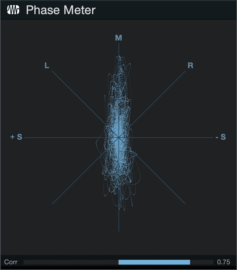
The Phase meter is helpful when checking stereo-playback issues and mono compatibility. There are two components to this meter: a large goniometer at the center of the plug-in window and a correlation meter at the very bottom.
The goniometer displays left versus right channel amplitude on several axes. A line in the following directions of the Goniometer display would mean:
- M-Axis: Mono signal
- +/-S Axis: Mono with one channel totally out-of-phase
- L/R Axes: Mono on one channel (left or right)
- M/S Axes: Channels in a Mid-Side (MS) encoded or recorded signal
The correlation meter shows the average amount of in-phase and out-of-phase audio signal. Correlation meter parameters are:
- +1: Mono signal
- -1: Reversed-phase mono signal
- 0: Independent signals (true stereo or dual mono)
Spectrum Meter
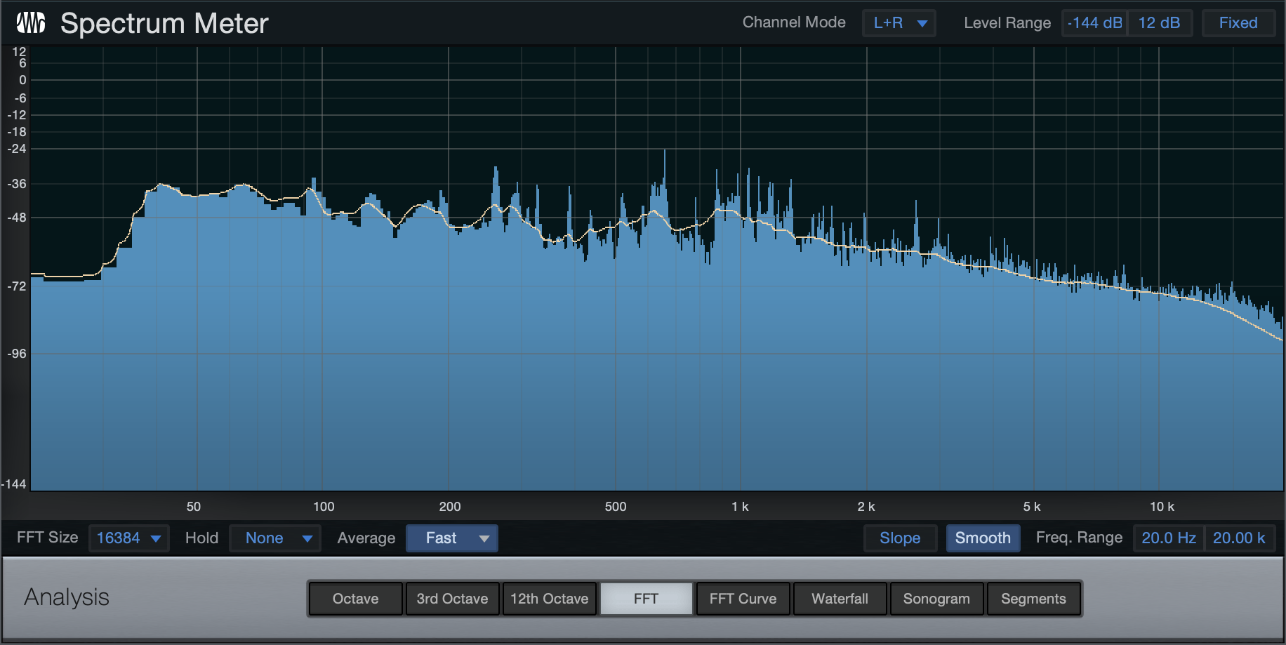
Spectrum Meter is helpful when determining the frequency content of an audio signal. For instance, you might know that a drum loop needs some EQ, but you might not be sure what frequencies to bring up or down. Or there might be an annoying ring in a guitar part that you want to get rid of but you do not know the frequency of the ring. Spectrum Meter can help diagnose these problems, and many others.
Spectrum Meter is fully adjustable using the following parameters at the bottom of the plug-in window:
Channels
When Spectrum Meter is inserted on a stereo Track, you can choose from the following channels to be analyzed in the meter:
- L: Left channel only
- R: Right channel only
- L+R: Sum of left and right channels
- L-R: Difference between left and right channels
When Spectrum Meter is inserted on a multichannel source, the Channel Modes you can choose to analyze from will vary, depending upon the source material. If inserted on an Audio Channel, the Channel Mode options are based on the Channel’s selected format (5.1, 7.1.2, etc.). If inserted on the Main Out of a Song using Dolby Atmos, the Channel Modes available are determined by the Bed Format selected in the Dolby Atmos Renderer.
Analysis Mode
- Octave: Octave Band displays frequency content divided into octaves, useful for determining broad balance across the frequency spectrum.
- 3rd Octave: Third-Octave Band displays frequency content divided into 1/3 of an octave, useful for determining balance with good precision across the frequency spectrum.
- 12th Octave: The bands in the 12th-octave meter correspond to the 12 musical tones in an octave, each in its appropriate place on a piano-like keyboard. This allows for easy reading of the pitch or note value of a given signal.
- FFT: A Fast Fourier Transform, or FFT, displays frequency content divided into many bands. It’s useful for accurate metering of a specific range of the frequency spectrum.
- When FFT is selected, you can select the FFT window size (FFT size = time vs. frequency resolution). You can choose from 16,384; 8,192; 4,096; and 2,048. The default setting is 16,384.
- As FFT measurements are divided into bands, exact frequencies across the entire spectrum are not measured.
- When using the FFT display, a -3 dB/octave line is displayed in addition to the frequency and level crosshair. This line represents compensation for the shrinking frequency-width of the FFT bands toward the higher end of the spectrum, which leads to a lower energy content. A well-balanced mix should somewhat approximate the slope of this line.
- FFT Curve: This performs the same analysis as the FFT mode, but displays the result as a single white line.
- Waterfall & Sonogram: Two modes that graph changes in frequency content and dynamics over time.
- Segments: Closely resembles the output of an FFT display. However, the X/Y grid is split up in uniform segments, rather than varying in resolution depending on frequency. Switchable amplitude segment sizes of 0.5, 1, and 2 dB.
Level Range
- Minimum Level: Minimum amplitude to be displayed for all frequencies. Variable from -144 dB to 6 dB less than the maximum level.
- Maximum Level: Maximum amplitude to be displayed for all frequencies. Variable from 0 dB to 6 dB more than the minimum level.
- Fixed: When engaged, five level ranges are available in the menu to the left: -50 dB, -72 dB, -96 dB, -120 dB, and -144 dB.
Note: You can also quickly change the Level Range by clicking and dragging vertically within the meter.
Frequency Range
- Minimum Frequency: Minimum frequency to be displayed. Variable from 20 Hz to within 10 Hz of the maximum frequency.
- Maximum Frequency: Maximum frequency to be displayed. Variable from 20 kHz to within 10 Hz of the minimum frequency.
The Min and Max Level/Freq values can be changed by typing in a new value, or by clicking-and-dragging up or down on the value.
Sidechain Input
To enable the sidechain feature, click the Sidechain button. This brings up a second spectrum display below the main display, showing the frequency content of any signal you route to the Spectrum Analyzer's sidechain. This lets you compare the frequency response of two different signals simultaneously, such as a rough mix and a reference track. For more information on routing signals to effect sidechains, see Sidechaining in the Effects Signal Routing section.
Tuner
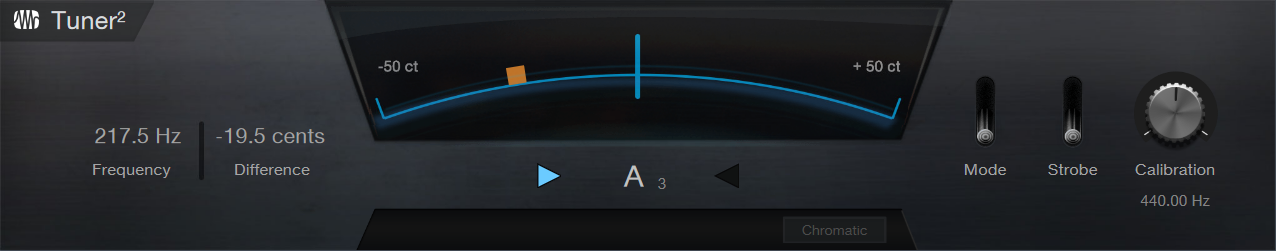
The Tuner proves invaluable when inserted on guitar, bass, and other instruments that require frequent tuning. Tuner features a switchable standard/strobe display, with exact Frequency and Difference readouts in the lower left corner.
The Meter located at the top center of the Tuner displays the tuning of the input sound’s pitch. Below this, a center-note indicator appears whenever you start playing. The indicator displays an arrow to either side. When the left arrow is displayed, the signal is tuned below the closest note; when the right arrow is displayed, the signal is tuned above the closest note. When neither of the arrows are displayed, the signal is perfectly tuned.
Click on the “Mode” toggle to switch between Chromatic and Custom tuning modes. Chromatic mode allows you to freely tune a string to any of the 12 pitches of the chromatic scale. Custom mode locks the tuner into a specific tuning. When Custom mode is toggled, you can pick the tuning from the dropdown menu underneath the meter. When the tuning is set, the tuner display is locked to included pitches only, making it easy to adjust specific tunings.
Click on the “Strobe” toggle switch to enable the strobe display. Strobe is excellent for intonation adjustments. To use a strobe tuner, play a note and observe the strobe bars on the indicator; if they are stationary, the note is in tune. If the strobe is moving, the note is either sharp (moving clockwise) or flat (moving counter-clockwise).
The Calibration knob enables calibrating the Tuner to a center frequency from 415 Hz to 465 Hz. There are also several calibration presets available from the Tuner preset list.
Level Meter
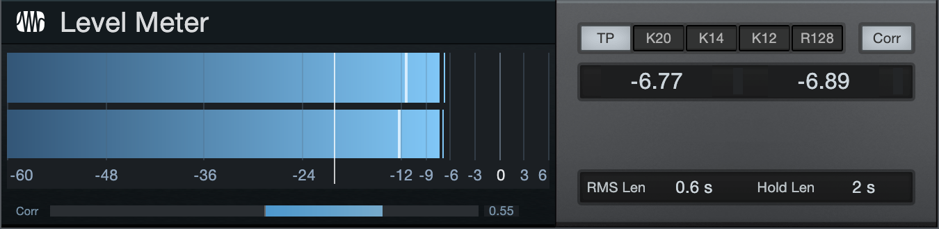
The Level Meter plug-in is a level meter that can be sized as a horizontal or vertical display type. The following parameters are available in the Level Meter:
- Mode: Select True Peak, K-20, K-14, K-12, or R128 (Loudness) metering mode.
- Corr: Engage to display phase correlation.
- RMS Len: Click the field and select an RMS length value from the menu.
- Hold Len: Click the field and select a Hold length value from the menu.
When Level Meter is inserted on a multichannel source, the number of individual channel levels displayed is dependent upon the source material. If inserted on an Audio Channel, the levels displayed are based on the Channel format. (5.1, 7.1.2, etc.). If inserted on the Main Out of a Song using Dolby Atmos, the channel levels displayed are determined by the Bed Format selected in the Dolby Atmos Renderer.

Scope

The Scope provides the functions an engineer would expect from a digital oscilloscope and is useful for debugging problems in the studio, such as analyzing crosstalk and noise levels.
There are three signal channels and one math channel. Each channel can either show the left or right signal of the Insert Channel, or sidechain input, while the math channel can show the difference between two of the signal channels. (B and C can be inverted to sum instead, or to do a polarity flip.)
Each of the color-coded channels can be scaled and offset in the Y axis, and scaling is shown as percent of full scale per division. (Full scale is 1.f, equivalent to 0 dB.) All channels can be activated/deactivated by clicking on the colored channel letter.
The time (x axis) can also be scaled and offset. This setting is for all channels. The offset is shown with a green vertical line.
The units follow the samples/seconds switch above the display, and can be expressed in decibels (dB) or percentages (-100% to 100%).
The scope is triggered from one of the following sources:
- Slope: Triggers when the signal level on the selected channel crosses a threshold level in the right direction. The threshold is adjusted by the Trigger Level control. Note that this does not apply to the Math channel.
- Transients: This uses the same audio channel, and the Slope and Level controls still apply, but the transient level is usually much more narrow: somewhere above 0% and typically around 1.5%.
- External Signals: Notes sent to the scope MIDI input or not sent at all (free).
Engaging Oneshot turns triggering off after the first received trigger. Retrig waits for one new trigger in case you get the wrong signal or change the signal.
The Scope display is latching, meaning that a signal is shown only on the second trigger. Note that the scope does not clear its buffer on stop, so there may be unwanted signal shown until another display trigger occurs.
The Hold control adjusts the length of time shown for a trigger signal, and during this period, no new signal triggers the scope. This is adjusted in percent of the display width and is also shown in the selected time unit and as a green vertical line. The display is clipped on a new trigger.
Finally, there is a crosshair for measuring the signals. It has a tool-tip readout using the units displayed in relation to the selected channel. Use this for measuring distances/differences for the selection, where dB levels are rectified signal levels, so you can compare positive and negative peak levels.
Tone Generator
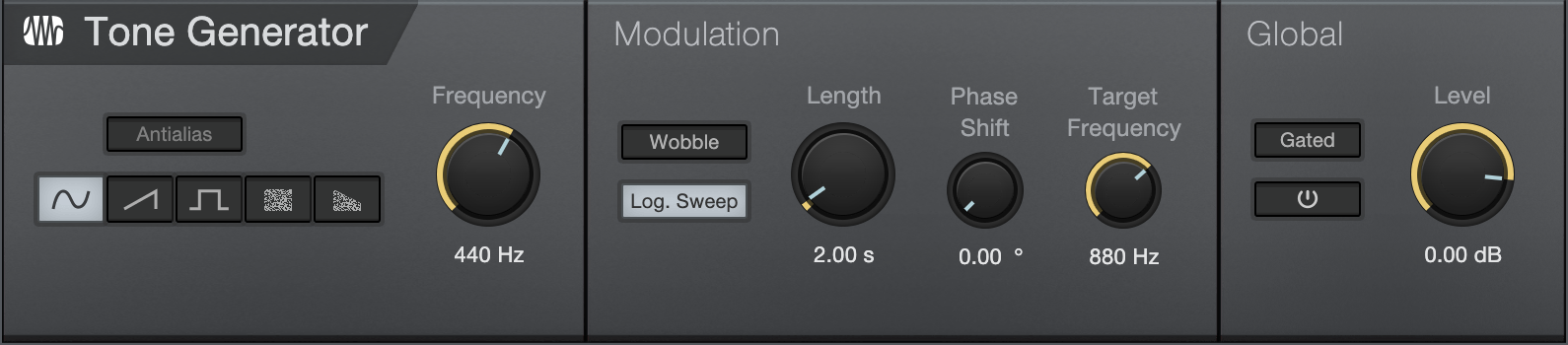
Tone Generator is capable of generating noise, frequency sweeps, and other signal types commonly used for signal-path testing and calibration. The Scope would commonly be used in conjunction with Tone Generator to analyze return signals at the end of the signal path being tested or calibrated.
The following parameters are available in Tone Generator:
- Waveform: Choose from sine, saw, square, white noise, and pink noise.
- Anti-Alias: The saw and square waveforms have Anti-Aliasing engaged by default in order to prevent aliasing artifacts from appearing.
- Frequency: Set the tone frequency from 1 Hz to 22 kHz.
- Modulation:
- Wobble: Engage this to make the tone frequency move from the set frequency to the modulation Target Frequency, according to the Modulation settings.
- Log. Sweep: Engage to make the frequency sweep logarithmic instead of linear.
- Length: Set the length in time of the sweep from Frequency to Target Frequency; range is from 10 ms to 60 seconds.
- Phase Shift: Set the phase shift that occurs over the chosen Length of time, from 0° to 180°.
- Target Frequency: The end frequency to which the tone is swept during modulation.
- Gated: Gated allows the output to be turned on via a note played on a Keyboard (set the output of an Instrument Track to Tone Generator).
- Off/On: The default setting is Off. On activates the Tone Generator.
- Level: The output level of Tone Generator, from -144 dB to +24 dB (Use caution!).
IR Maker
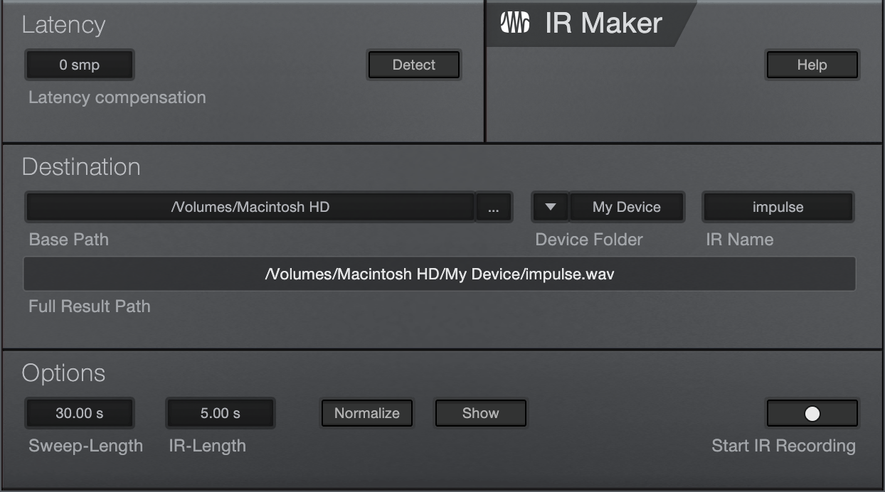
IR Maker is a utility plug-in that allows you to capture your own impulse responses for use with OpenAIR and with the cabinet section of Ampire. The following describes general guidelines on how to use IR Maker to create impulses:
- In the Song/Song Setup/Audio IO Setup menu, create an Output Channel configured with the physical output on your interface that the IR Maker sweep signal routes through. That output might be connected to a speaker in the space for which you want to capture an IR, or to the Effects Return on an amplifier connected to a cabinet for capturing a guitar cabinet IR.
- Then, create an Input Channel in Song/Audio IO Setup, configured with the physical input on your interface that IR Maker gets the return signal from. A microphone, or the output of a hardware processor, connects to this input when capturing the IR.
- Now create an Audio Track in a Song, set its input and output to the Input and Output you just created, and insert IR Maker on the Track.
- Signal-path latency is important. That latency may vary because of the distance of the mic from the source, for instance, and may be a part of the impulse response to be captured. So, it is easiest to detect the signal path latency with a loopback from interface output to interface input. To do this, you need to route the physical output directly into the physical input, creating a loopback for the I/O you created before. Then, press Detect in the Latency Compensation section. If the latency box still shows zero after testing, then something is wrong with your audio setup (levels, audio I/O ports, monitors, cables, interface settings, etc.).
- After detecting latency in the signal path, disconnect the loopback from before. Connect the output to the device that receives/outputs the IR Sweep signal (a speaker in a room, a guitar amplifier Effects Return, etc.), and the input to the device that captures the IR (a microphone in a room or in front of a guitar cabinet, or the output of a hardware device).
- The file Output Path is structured as a base part (the path to the folder where your IRs reside), a device part (the subfolder for that cabinet, space, etc.), and an IR base-name (mic/mic-position).
- Select the Sweep Length (longer = higher-frequency resolution and less noise). In general, 60 seconds should be enough for high fidelity. IR Length can always be shortened later to save CPU resources but it should be long enough to contain the whole response. As a default for cabinets, we recommend using 0.1 s. Shorter Sweep and IR Lengths get calculated much faster.
- Normalizing ensures maximum loudness in IR but can be done later, and can destroy loudness relationships between different devices.
- Usually you need to trigger the sweeping several times to adjust the levels. It helps to show Input and Output Channels in the mixer to watch the metering closely.
- Check the Open checkbox to have your computer's file browser open the newly created impulse response after calculation. You can then drag that onto a new Track to view the IR and make any edits you desire, such as fades; or drag the IR into OpenAIR or Ampire for immediate use.
Mixtool
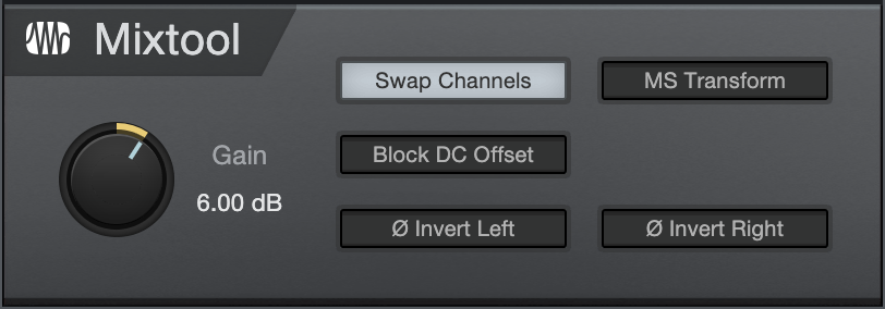
Mixtool provides common track utilities, including independent left- and right-channel inversion, left- and right-channel swap, and MS transformation of stereo signals. Use Mixtool when inverting channels to correct for phase cancellation and correlation issues, as well as to provide MS transformation to decode signals recorded with Mid-Side stereo configurations.
The following parameters are available for Mixtool when used on a stereo Track:
- Gain: Set overall output Gain. Variable from -24 dB to +24 dB. Use [Ctrl]/[Cmd]+[Shift] and drag to fine-tune the value.
- Swap Channels: Click to swap left and right Mixtool input channels. Stereo Tracks only.
- MS Transform: Click to perform a Mid-Side transform on the Mixtool input channels. Stereo Tracks only. Generally used to decode MS-recorded signals or to create MS signals for stereo image processing.
- Block DC Offset: Re-centers the incoming waveform, to remove any DC Offset in the audio signal.
- Invert Left: Click to invert the phase of the left playback channel for a stereo Track.
- Invert Right: Click to invert the phase of the right playback channel for a stereo Track.
MixTool is enhanced for use with multichannel audio. When assigned to a multi-channel source, MixTool will display adjustable faders with optional phase inversion, Solo, and Mute available for each output.
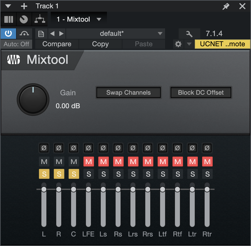
When used on a mono Track, the Mixtool plug-in has one control to invert the phase of the signal.